This project was for my MET 245 class where we manufactured a hammer and wrote G-code for an engraving on each side of the hammer.
Product
We used a variety of processes in order to create a hammerhead as well as the hammer handle. For the hammerhead we used a 1 in hexagonal bar made of 1020 steel and a 6061-T6 aluminum rod for the handle. Each piece was cut and finished to the specified dimensions. After working in the lab to make the parts for a several weeks we moved to a computer lab where we used the cutdata application which provided recommended speed, feed rate, and DOC for each process. These values were compared to the actual values used in lab. the values were not always exact, but they were always usually relatively close.
Key Subassemblies
G-code
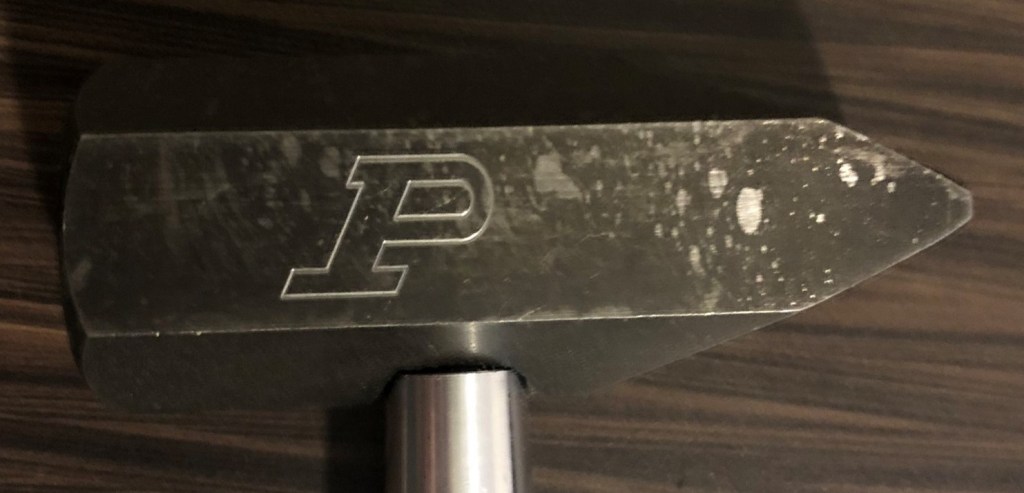
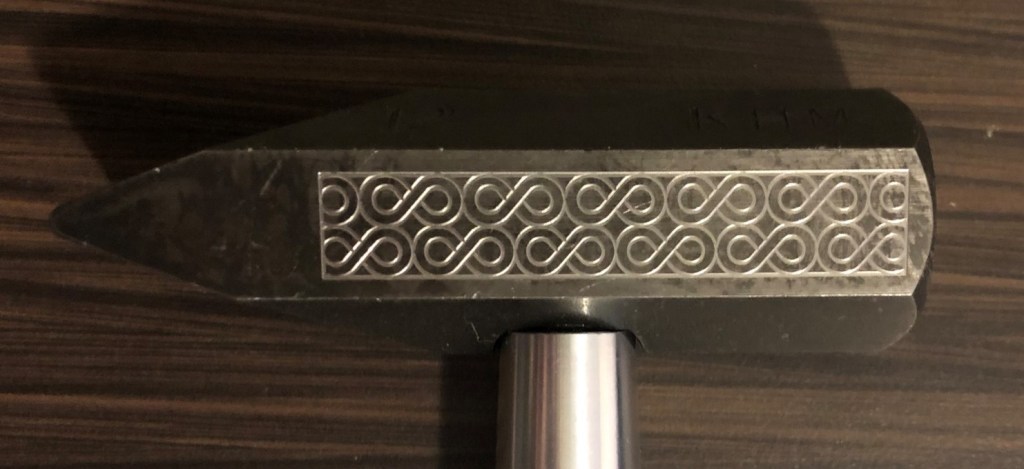
To create my tool paths, I drew both of my designs in SolidWorks. On my first side, I decided to do the Purdue P; this was a generally simple design, but I feel it suits the project well. On the second side, I created an infinity sign pattern that covers the side of the hammer. Using SolidWorks made this project exponentially easier as after I got my drawing modeled, the process became finding the points using a tool on SolidWorks. Then putting those coordinates with the corresponding G-code command (G01, G02, or G03). Another advantage I found using SolidWorks was a lack of trial and error.
Manufacturing
This was the first time I had manufactured a metal product, so it was a great learning experience working with the machines. Along with learning how the machines work I also learned how to operate them safely. Several different processes were used throughout the manufacturing of the hammer. The machines used for the hammer were: Vertical band saw, horizontal and vertical mills, grinders, and a lathe. Other processes were applied to the part like tapping, stamping, and surface treating the hammer head.