This was a group project for my MET 213 class. We were instructed to make an RC glider that is able to fly over 30 meters and can be controlled using a controller.
Full Assembly
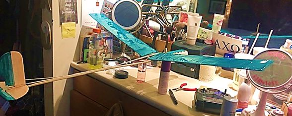
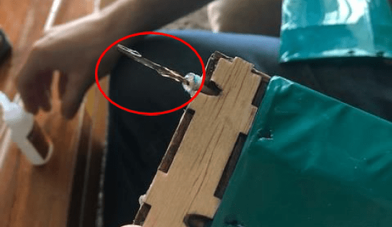
Going in to this project I had very little knowledge on how airplanes are able to fly. I had a general understanding of topics like lift, drag, and, center of gravity but when topics like aerofoil I was lost. The glider went through several revisions. Originally the glider was built without electronics or aerofoil, we quickly discovered that both would be necessary for the glider to fly. The glider’s aerofoil were modeled in Autodesk Inventor. When testing the glider it could typically flow 30 meters or more. Unfortunately when we were testing it for a grade, on the first throw it dove down to the right and broke the right wing off. We ended up make a quick fix by drilling a hole in the dowel that was holding the wing and super gluing the drill bit inside the broken dowel rod. Following that fix it was flying the best it ever had, until the other wing and the skeleton of it broke.
Key Features
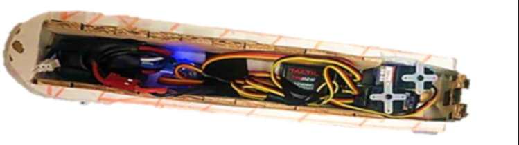
Fuselage
The fuselage was made to hold all of the RC components for the glider. The fuselage consisted of a foam casing, a laser cut balsa wood box, a 7.4 V battery, a Voltage regulator 2 servo motors, a receiver, and 2 push rods. The foam casing was made to make the glider more aerodynamic and to lighten the impact during a crash.The laser cut balsa wood box is to protect and enclose all the electronics. The voltage regulator was needed because the receiver and servo motors had a maximum voltage of 5 V. Attached to each servo motor was a push rod used to control the flaps on the wings, so the Rudder and elevator can be controlled. Lastly the receiver was in the fuselage to receive inputs from an RC controller and relay them to the servo motors.
Physical

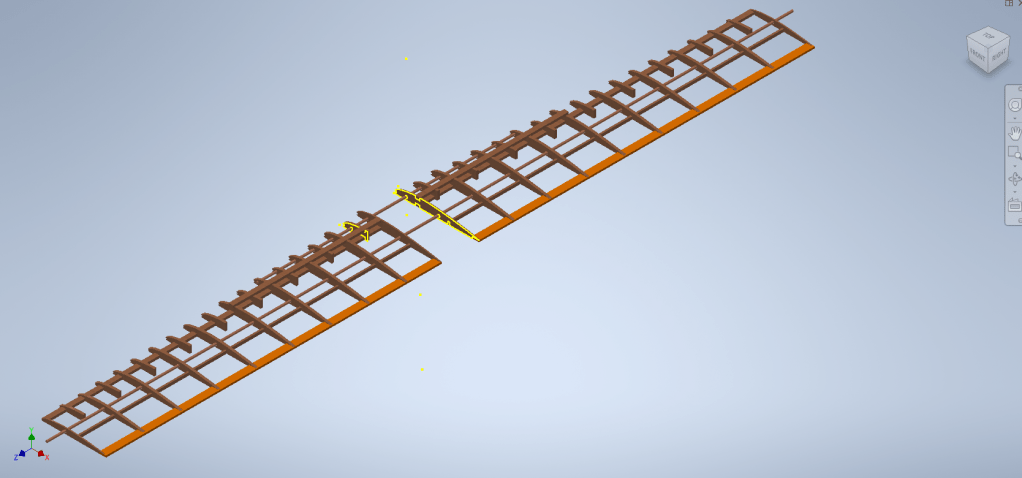
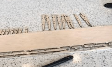
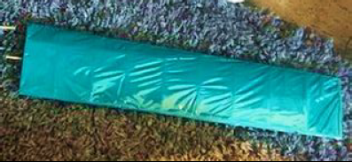
Wings
The wings went through several design iterations, originally they were just two pieces of balsa wood with the front the the wing sanded down to be round for better aerodynamic performance. We found that the aerofoil needs to be much more precise than sanding. With the help of my professor the airfoil model was created. After laser cutting each rib, and cutting the dowel rods to size, the parts were put together to make the wings skeleton. Following that Monokote was wrapped around the wing’s skeleton to create the wings surface.
Models
Physical
Report
Click below to download our report for the project.
